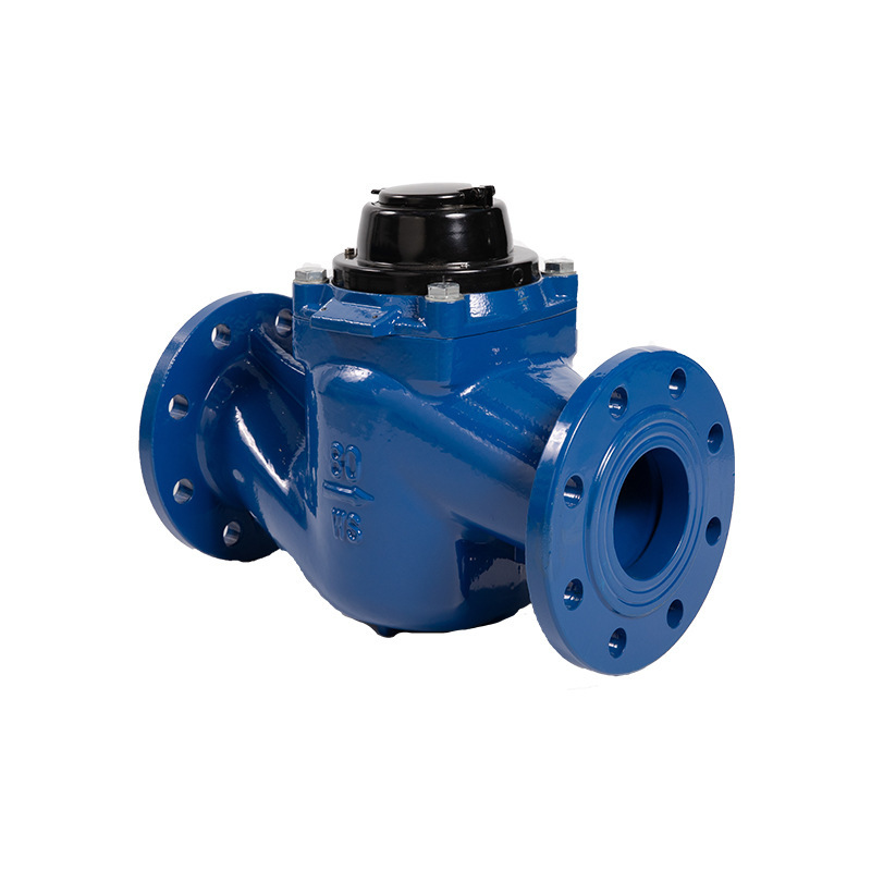
Vertical Screw Type Water Meter


Production Description
● Ball bearing design, high sensitivity of water meter, free rolling balls can convert wear points and improve service life.
● Large impeller, low speed design, can withstand larger flow.
● The design of the return cavity of the case can make the pressure loss in the range of the horizontal screw type water meter.
● Built-in stainless steel filter, anti-jamming and anti-sand.
● Optimized drive shaft design to eliminate weak links in water meters.
● Accurate measurement and long use time.
● Full flow detection, accurate measurement, overall performance is better than conventional mechanical water meters, wide range, suitable for places with large flow changes.
● Equipped with passive direct reading counter, can support RS-485 or M-BUS standard interface, optional water meter with PN10, PN16, PN25 working pressure level.
● The impeller part comes with a stainless steel filter to prevent the water meter from being stuck due to foreign objects.
● Worry-resistant bearing system. The measurement is stable, the use time is long, and the service life of the product is significantly improved.
● Flange sealing is strong and pressure loss is small.
● Built-in stainless steel filter. No need for additional filters, it is suitable for domestic water environment, and it is suitable for water metering in occasions with large flow changes.
● All copper material. The all-copper material is more resistant to oxidation, not easy to rust, and prolongs the service life.
● The multi-pointer dial water meter is accurate to zero point zero zero tons, remembering the usage of every drop of water for you.
● There is a substance similar to “rust” at the joint of the water meter. In order to prevent the product from rusting, we apply a layer of anti-rust paint on the surface to prevent the product from rusting.
Application Area
The vertical screw-wing water meter is used to measure the water volume of the pipe network.
Product Specifications
|
The nominal caliber |
Overload flow |
Commonly used traffic |
Q3/Q1 |
Q2/Q1 |
Departmental flow |
minimum flow |
|
DN40 |
31.25 |
25 |
100 |
1.6 |
0.4 |
0.25 |
|
DN50 |
50 |
40 |
100 |
1.6 |
0.64 |
0.4 |
|
6.3 |
2.52 |
|||||
|
125 |
1.6 |
0.52 |
0.32 |
|||
|
6.3 |
2.02 |
|||||
|
160 |
1.6 |
0.4 |
0.25 |
|||
|
6.3 |
1.58 |
|||||
|
200 |
1.6 |
0.32 |
0.2 |
|||
|
6.3 |
1.26 |
|||||
|
DN80 |
78.75 |
63 |
100 |
1.6 |
1 |
0.63 |
|
6.3 |
4 |
|||||
|
125 |
1.6 |
0.8 |
0.5 |
|||
|
6.3 |
3.18 |
|||||
|
160 |
1.6 |
0.64 |
0.4 |
|||
|
83 |
2.48 |
|||||
|
200 |
1.6 |
0.5 |
0.32 |
|||
|
6.3 |
2 |
|||||
|
DN100 |
125 |
100 |
100 |
1.6 |
1.6 |
l |
|
6.3 |
6.3 |
|||||
|
125 |
1.6 |
1.28 |
0.8 |
|||
|
6.3 |
5.04 |
|||||
|
160 |
1.6 |
1 |
0.63 |
|||
|
6.3 |
3.94 |
|||||
|
200 |
1.6 |
0.8 |
0.5 |
|||
|
6.3 |
3.15 |
|||||
|
DN150 |
312.5 |
250 |
100 |
1.6 |
4 |
2.5 |
|
6.3 |
15.75 |
|||||
|
125 |
1.6 |
3.2 |
2 |
|||
|
6.3 |
12.6 |
|||||
|
160 |
1.6 |
2.5 |
1.57 |
|||
|
6.3 |
9.85 |
|||||
|
200 |
1.6 |
2 |
1.25 |
|||
|
2.5 |
3.125 |
|||||
|
4 |
s |
|||||
|
6.3 |
7.88 |
|||||
|
250 |
1.6 |
1.6 |
1 |
|||
|
2.5 |
2.5 |
|||||
|
4 |
4 |
|||||
|
6.3 |
6.3 |
|||||
|
315 |
1.6 |
1.27 |
0.8 |
|||
|
2.5 |
2 |
|||||
|
4 |
3.18 |
|||||
|
6.3 |
5 |
|||||
|
400 |
1.6 |
1 |
0.63 |
|||
|
2.5 |
1.57 |
|||||
|
4 |
2.5 |
|||||
|
6.3 |
3.94 |
Product Display